The biggest rule for home automation is not to change existing behavior of users that causes inconvenience or frustration. Which is a rule that easily forgotten. Let's use the classic example of a smart light bulb in a living room. A user typically flips a switch to turn on and off a light. Now they have to ask Alexa, Google, or use an app on their phone. This is bad.

It's causing an inconvenience because the user can't flip a switch.
Solutions
The 2 common solutions presented in this situation:
1. Blocking the user with tape or other mechanism. Checkout Thingiverse to see how common this is: https://www.thingiverse.com/tag:Light_Switch_Cover. This changes user behavior so it's a bad idea.
2. Replacing the light switch with a smarter one. This is the best option but requires a hardware replacement of the light switch. Which may not be possible, costly and potential dangerous to do-it-yourself!
3. A third hybrid solution: Trigger the smart device with the existing light switch using power wall outlet as feedback using an Arduino device with WiFi. In this solution, the light switch changes the power state of the outlet that the Arduino based micro controller is monitoring. When the light switch is turn on/off it changes the power to the Arduino analog voltage GPIO pin. That sends a message off to a home assistance to notify the smart device. In US based homes, the 2nd wall outlet still has power so it provides constant power to the device. Here is a diagram to get an idea of the flow to toggle the smart bulb state from a user.
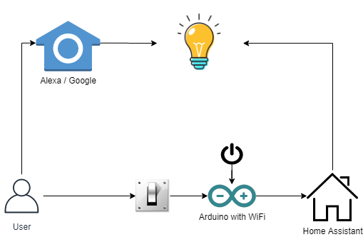
The advantages:
- Simple & low effort
- Use existing switches to make them smart
- Ability to control multiple devices with a single switch
- Open source
Building the Device
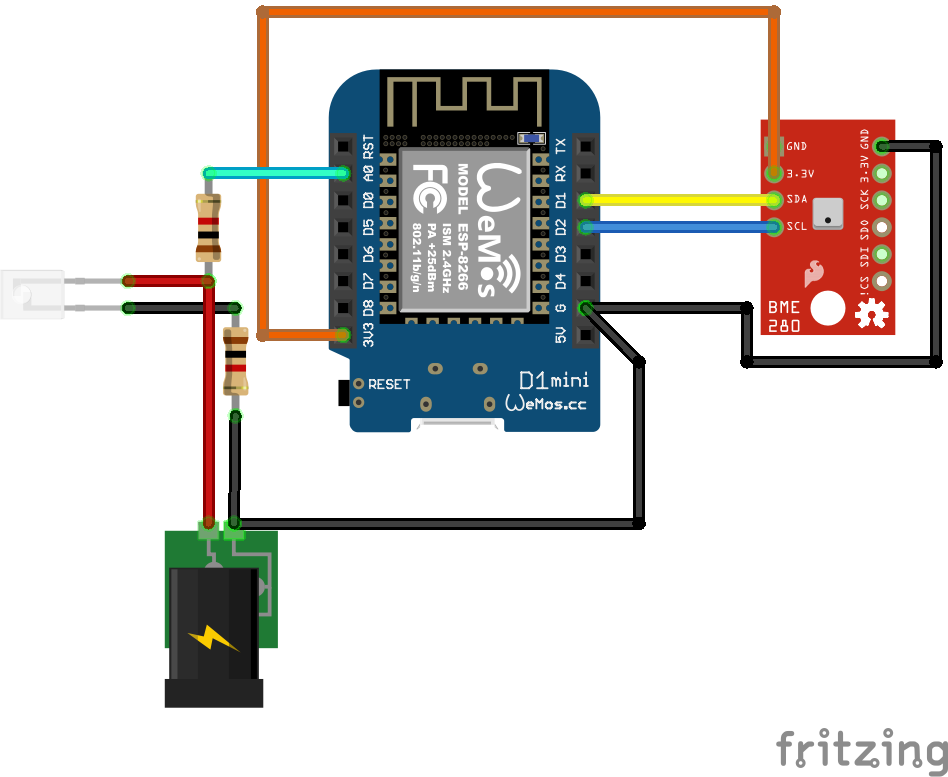
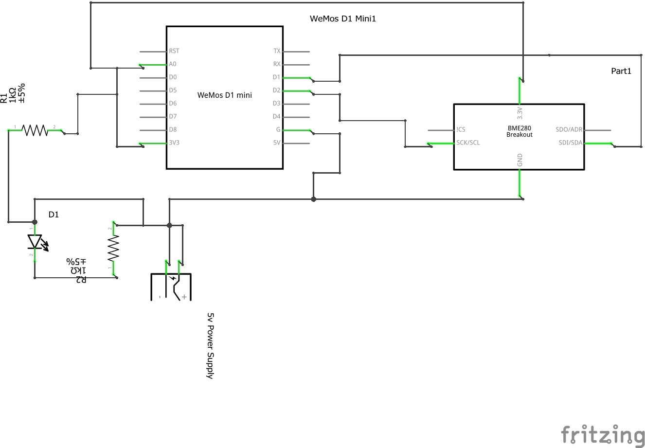
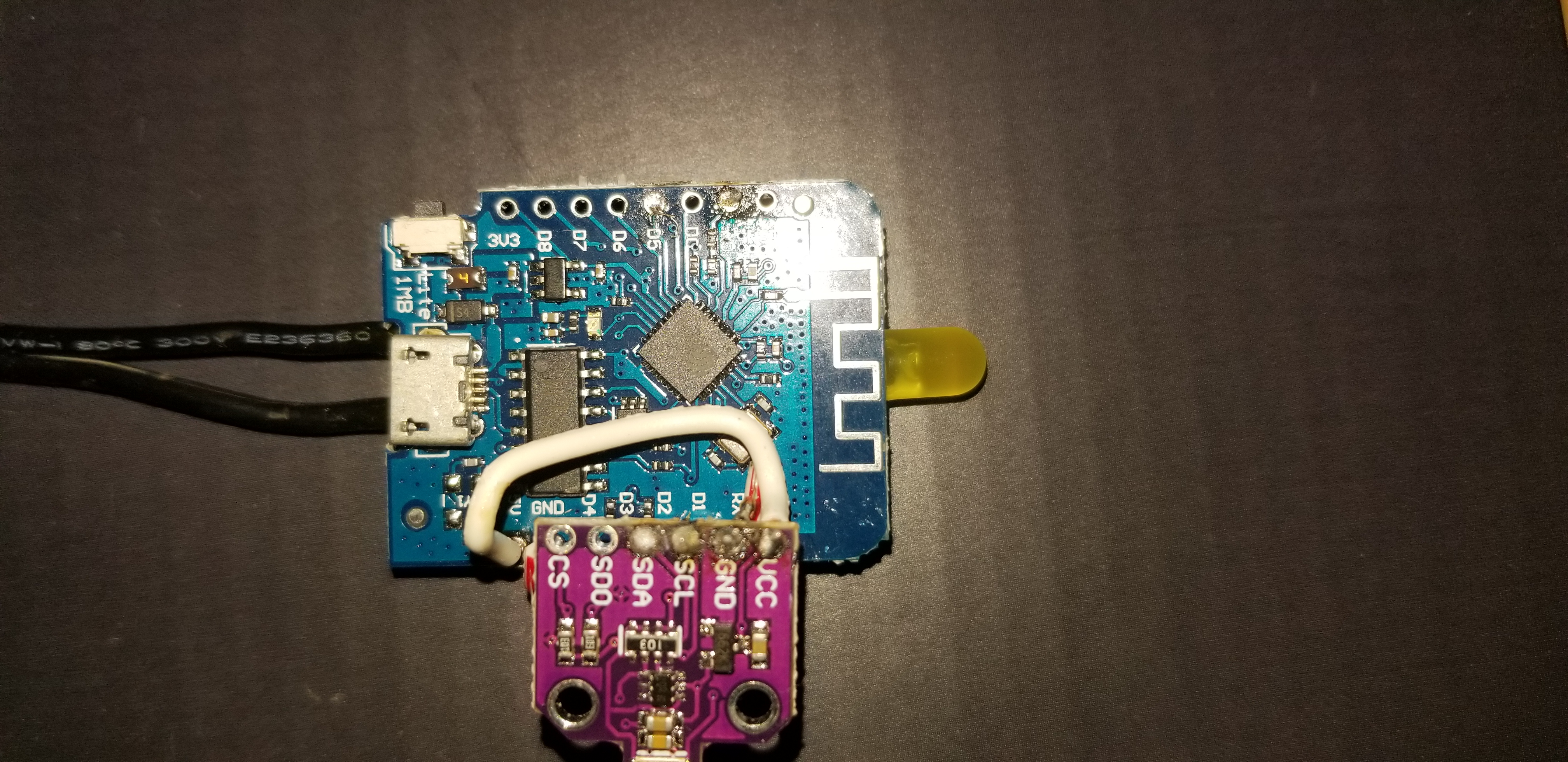
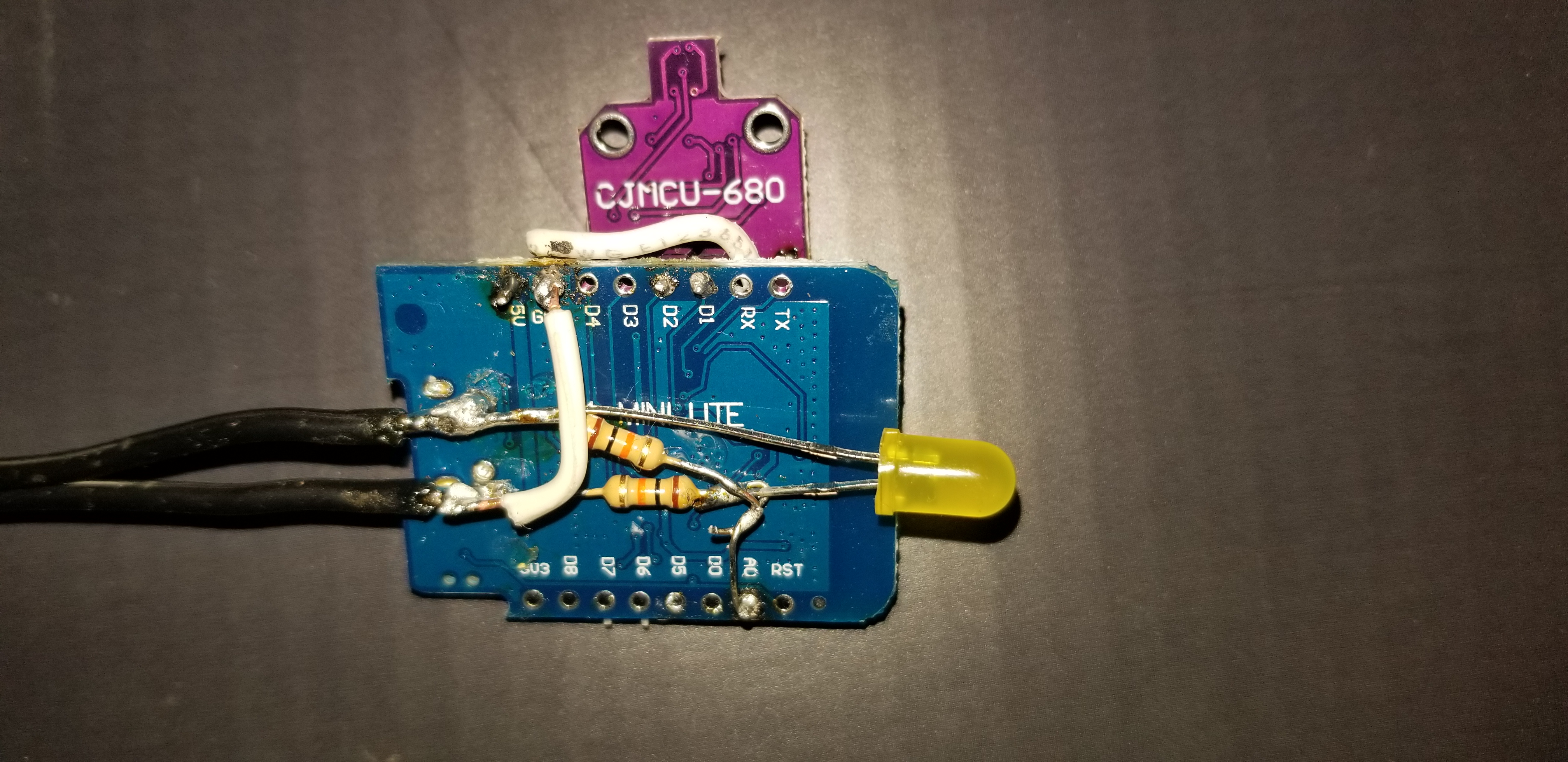
Step 1: Get the Components and Solder Them
Tools
- Soldering iron
- Third hand or vise
Material
- Wemos mini d1 from Amazon or similar esp8266 / esp32 device
- 2 x resistors (any two usually works, i used 10k)
- Wire
- 2 5v usb wall chargers.
- 1 male usb plugin
- 1 regular usb charging cable for the esp32.
- led
- solder
- (optional) bme280 or bme680
Step 2: Download and Upload Software
Flash your device with a Tasmota firmware.
Tasmota Module configuration
Set to: Generic Module then click Save. the device will restart.
- D2 - I2C SDA (6) - BME680
- D1 - I2C SCL (5) - BME680
- A0 - Analog (1) - connected to 5V power supply resistor divider
Tasmota Console
Send when external light switch power is on, send 1.
Rule1 ON analog#a0>1000 DO Backlog Rule1 0; Rule2 1; Publish cmnd/masterlight/SWITCH 1 ENDON
When external light switch power is off, send 0.
Rule2 ON analog#a0<1000 DO Backlog Rule1 1; Rule2 0; Publish cmnd/masterlight/SWITCH 0 ENDON
Enable rule 1: Rule1 1
Ensure you have MQTT enable then look at the console for messages similar to this:
01:39:26 MQT: stat/tasmota_A61989/POWER1 = ON
01:39:26 RUL: POWER1#STATE=1 performs "Backlog Delay 10; Power1 0"
01:39:26 MQT: stat/tasmota_A61989/RESULT = {"Delay":10}
01:39:26 RUL: SWITCH2#STATE performs "Publish cmnd/garagedoor/SWITCH 0"
01:39:26 MQT: cmnd/garagedoor/SWITCH = 0
01:39:26 MQT: stat/tasmota_A61989/RESULT = {"POWER1":"OFF"}
01:39:26 MQT: stat/tasmota_A61989/POWER1 = OFF
1:40:11 MQT: tele/tasmota_A61989/STATE = {"Time":"2020-06-26T01:40:11","Uptime":"6T03:00:30","UptimeSec":529230,"Heap":23,"SleepMode":"Dynamic","Sleep":50,"LoadAvg":19,"MqttCount":1,"POWER1":"OFF","POWER2":"OFF","Wifi":{"AP":1,"SSId":"lucky","BSSId":"4C:ED:FB:7B:4A:98","Channel":4,"RSSI":100,"Signal":-34,"LinkCount":1,"Downtime":"0T00:00:05"}}
01:40:11 MQT: tele/tasmota_A61989/SENSOR = {"Time":"2020-06-26T01:40:11","Switch2":"OFF"}
The MQTT topic is cmnd/masterlight/SWITCH with a boolean value of either 1 for open or 0 for close. The topics are for state or the reed switch sensor value Switch2 that are sent every 5 minutes (configurable) via MQTT.
Step 3: Add to a Home Assistance
So here comes the part that could change per user preferences. I'm using NodeRed but this could be done with other home assistance software. Get the MQTT message then process notifications you would like.

Resources
https://learn.adafruit.com/adafruit-bme680-humidity-temperature-barometic-pressure-voc-gas/arduino-wiring-test https://www.bosch-sensortec.com/products/environmental-sensors/gas-sensors-bme680/ https://lastminuteengineers.com/bme280-arduino-tutorial/
